Ohm's Law Explained: Understanding Voltage, Current and Resistance
Explore the fundamentals of Ohm's law in electrical circuits. Learn how voltage, current and resistance interact, and discover practical examples of series and parallel circuits. Understand the difference between ohmic and non-ohmic materials and see how this simple relationship shapes modern electronics.

Understanding Ohm's Law: The Foundation of Electricity
Ohm's law is one of the first equations students of science and engineering encounter because it encapsulates the relationship between three fundamental electrical quantities: voltage, current, and resistance. Even if you're not an electrician, you use devices governed by this law every day. Everything from the charging cable that powers your smartphone to the dimmer switch that changes the brightness of a lamp relies on a balance of voltage and current through resistive elements. By understanding how these quantities interact, you can make sense of why appliances behave the way they do and why certain safety measures exist in the home.
The Core Concepts: Voltage, Current, and Resistance
To appreciate Ohm's law, it helps to unpack its constituent terms.
-
Voltage () is a measure of electrical potential difference between two points. It tells us how much potential energy per unit charge is available to push electrons through a circuit. In everyday life, you might encounter 1.5-volt batteries powering a remote control or 220-volt mains electricity in household outlets.
-
Current () is the flow rate of electric charge, measured in amperes (amps). A larger current means more electrons are moving through a wire every second.
-
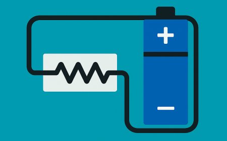
Resistance (), measured in ohms (), quantifies how much a material opposes this flow. A high resistance material restricts current, while a low resistance material allows more current to pass for a given voltage.
An intuitive way to visualize these concepts is to think of electricity like water in a plumbing system. Voltage is analogous to water pressure, current corresponds to the flow rate, and resistance is like the narrowing of a pipe that limits how much water can flow. As with water, increasing the pressure (voltage) will push more fluid through the pipe, but if the pipe is narrow (high resistance), the flow (current) will still be limited. This analogy helps highlight the interdependence of the three quantities and sets the stage for Ohm's law.
The Equation and Circuit Types
Georg Simon Ohm, a German physicist, formalized the relationship among voltage, current, and resistance in the early nineteenth century. The law states that the potential difference across a conductor is directly proportional to the current flowing through it, with the constant of proportionality being the resistance.
Mathematically, this is expressed as:
Where:
-
is voltage in volts ()
-
is current in amperes ()
-
is resistance in ohms ()
If two of these quantities are known, the third can be calculated. For instance, a 10-ohm resistor with 2 amps of current flowing through it must have 20 volts across its terminals. The power of Ohm's law lies in its ability to predict circuit behavior. If you double the applied voltage across an ohmic resistor, the current doubles as well because the resistance remains constant. Conversely, increasing the resistance while holding voltage constant will decrease current proportionally.
Series and Parallel Networks
Real-world devices seldom consist of a single resistor. Instead, components are connected in networks that can be categorized as series or parallel.
-
Series Circuits: Components are linked end-to-end so that the same current flows through each one. The total resistance is the sum of the individual resistances:
* Parallel Circuits: These circuits provide multiple paths for current to travel. Components share the same voltage, but the current divides between them. The total resistance is found by adding the reciprocals:
Household electrical outlets are wired in parallel so that each appliance receives the same voltage, and one device turning off does not cut power to the others.
Applications, Safety, and Non-Ohmic Devices
Ohm's law permeates nearly every aspect of electrical engineering and consumer electronics, but it's important to know its limits.
Ohmic vs. Non-Ohmic Behavior
-
Ohmic Devices: Components whose voltage–current relationship remains linear and passes through the origin are said to be ohmic. Typical resistors and metal wires fit this category.
-
Non-Ohmic Devices: These devices exhibit a nonlinear relationship, meaning their resistance changes with voltage, current, or temperature. Examples include semiconductor diodes, whose current-voltage curve is exponential, and incandescent light bulbs, whose filament resistance increases significantly as it heats up. Thermistors (temperature-dependent resistors) are another key example, often used as sensors.
Real-World Use and Safety
Ohm's law is fundamental to both design and safety. For example, when you plug in your laptop charger, the adapter is designed to provide a specific voltage. The laptop then draws the necessary current based on its internal resistance.
To prevent components from overheating and failing if too much current flows, devices include fuses or circuit breakers that cut off power when the current exceeds a safe limit. This protection mechanism directly relies on the predictable relationship between current, voltage, and resistance defined by Ohm's law. Furthermore, devices like dimmer switches and volume controls on radios use variable resistors (rheostats and potentiometers) to manually adjust resistance, thereby regulating the current and the device's output.
What's Your Reaction?


